Using Microswitches
Microswitches are available in your BEST consumable kit. A microswitch is a small momentary push switch that can close or open a circuit, depending upon how you wire it. There are three lugs on the microswitch. There is a common, a NO (normally-open) and a NC (normally-closed). The NO and NC refer to the state of the switch when the lever is NOT depressed (i.e., the normal position). Switches can be used for many things but here we are describing how to attach the microswitch to a digital input on your Gizmo. The Gizmo can then READ the value of the switch to determine if it is open or closed.
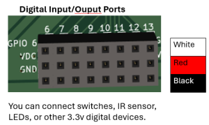
The General Purpose I/O ports (GPIO) ports on the Gizmo are digital ports. Digital signals are either high or low. On the Gizmo, a high signal is 3.3 volts and a low signal is 0 volts (or “ground”). The sensors we connect to the GPIO ports drive the signal to one of these voltages. If nothing is connected to the port, it will effectively read random values.
When connecting switches to your Gizmo, you can use either a 2-wire connection or a 3-wire connection.
Wire your switch circuit as described in the options below, depending upon how you plan to use it. You may solder wires to the lugs of your microswitch or use connectors (if provided). Then insert the bare-wire end of each into the (white) screw terminal connector so that the correct switch lug is connected to the desired wire of the interface cable.
NEVER wire your microswitch such that it shorts the 3.3V and GND rows of the GPIO port together. The COMMON terminal (lug) of the switch should always be connected to the GPIO (white wire).
The code you use to read the switch is different between the two setups. Read more about how to manage your software when reading digital inputs in the Arduino Programming for Gizmo – How to Read Sensors lesson.
Using Two Wires
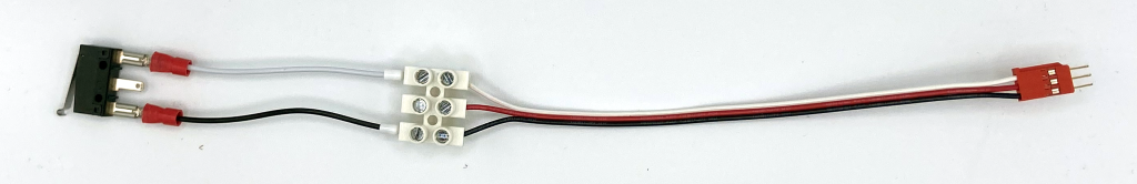
When connecting a limit switch with two wires, use only the white (signal) and black (ground) wires. The most common setup has the white wire connected to the switch’s common (COM) pin and the black wire connected to the switch’s normally closed (NC) pin. In this configuration with the limit switch pressed, the switch will leave the circuit open and the pull-up resistor will drive the port high. When the switch is released, it will close the circuit and drive the port low.
NOTE: Using the normally open (NO) pin on your limit switch, instead of the normally closed pin will just flip behavior of the switch. It will read high in software when released and low when pressed.
Using Three Wires
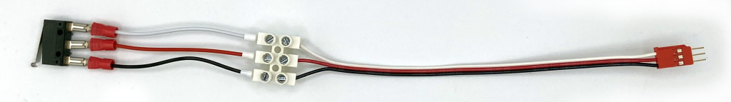
When using three wires with your microswitch, you want to connect it to one of the 8 3-wire General Purpose Input/Output (GPIO) ports using a 3-wire screw terminal sensor interface cable. The 3-wire screw terminal sensor interface cable has a 3 pin connector on one end and a 3-wire screw-terminal block on the other.
For this scenario, the switch itself will drive the port in both directions. The most common setup connects the white wire to the switch’s common (COM) pin, the red wire to the switch’s normally open (NO) pin, and the black wire to the switch’s normally closed (NC) pin.
ALWAYS use the white wire on the switch’s common pin. Otherwise, you risk shorting the GPIO power voltage (red wire) to ground (black wire) and will likely damage your Gizmo.
Note: If you swap the wires such that red is on normally closed and black is on normally open, the behavior of your switch will flip. It will read high when the switch is released and low when the switch is pressed.
Build the switch circuit that you desire as described above. Make sure that Gizmo power is off or the battery is unplugged. Now insert the 3 pin connector into any of the Digital I/O ports 1-8. Insert it with the white wire on the top of the socket, when looking at the Gizmo with LEDs on the left-hand.
The socket for GPIO has rows labeled GPIO, 3.3V, GND. The white wire on your 3-wire screw terminal sensor interface cable should plug into the GPIO row. The red should plug into the 3.3V row and the black should plug into the GND row.