There are two conditions when you need to power your Gizmo.
When uploading a program to either the System Processor or Student Processor.
When driving the robot, running the uploaded program.
Power when programming your Gizmo
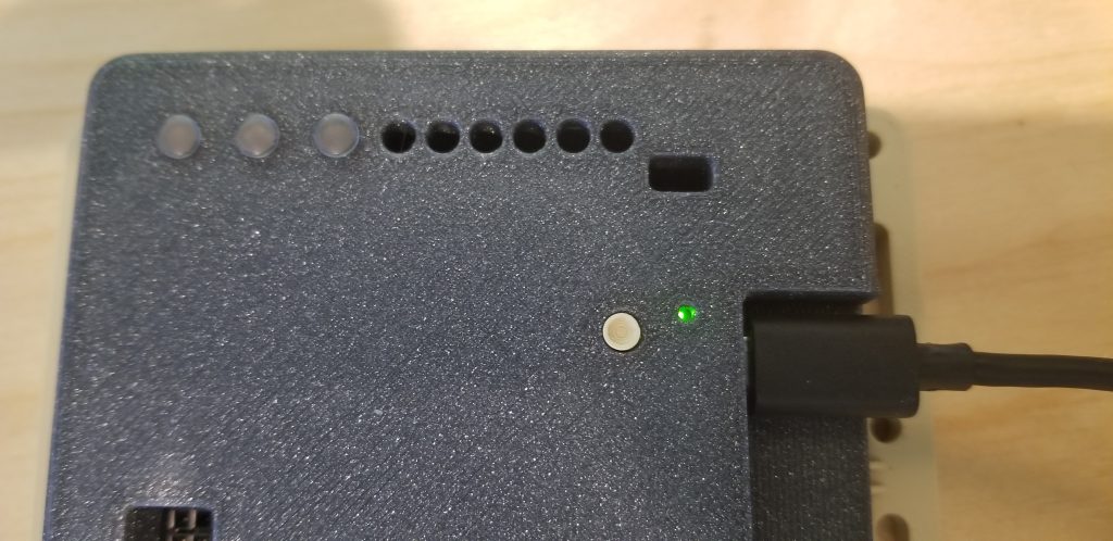
When uploading a program to your robot, you connect a USB cable to the processor you are uploading the program to (System Processor or Student Processor). In most cases, you will only be uploading to the Student Processor. When the USB cable is connected, it provides the necessary power to the PICO microcontroller for the upload operation. So, you DON’T need to even have your 7.2V robot battery connected at all. The LED on the PICO being programmed will flash indicating the upload activity and letting you know that it is powered.
Power when driving your robot
After you have uploaded a program to the Student Processor and are ready to drive your robot, then you will need the 7.2V robot battery connected.
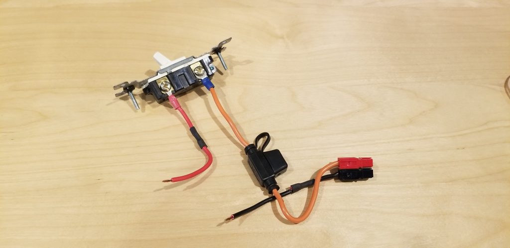
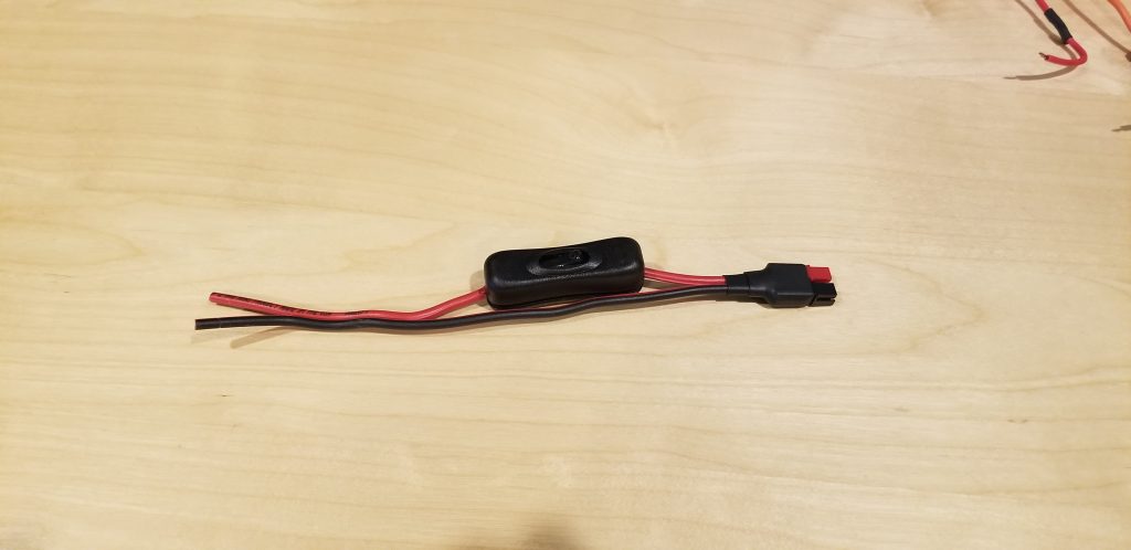
Your BEST Return kit contains a premade battery cable with inline switch like one of these:
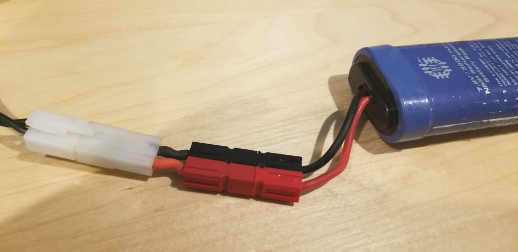
If you are working with Gizmo outside of the BEST program, you will need to create a battery cable like one of the above to power your Gizmo board. Your off-the-shelf RC 7.2V battery also may have a white Kyosho connector instead of the red/black powerpole connectors. The BEST program modifies these standard RC batteries because the Kyosho connectors wear out very fast. You can see how to modify these battery connectors in our guide here.
Charging the robot battery
Be certain that the kyosho (white) to powerpole (red/black) adapter is connected to your 7.2V battery charger kyosho (white) connector. The adapter should remain connected to the charger indefinitely and not removed. Always connect/disconnect your battery at the red/black powerpole connector, and never at the white connector.
Connect the red/black powerpole connector on your 7.2V battery to the corresponding red/black powerpole connector (adapter) on the battery charger. There is only one way the connectors will fit together. Red and black of each connector should always match; if they do not match, don’t plug it in!
Plug the battery charger into a 120v wall outlet. You may set the battery charger switch to fast charge or slow charge. For fast charge, be certain to monitor the battery charger and battery. A red LED will illuminate when charging is in progress. Continue charging until the LED turns green.
Connecting a battery to Gizmo
Only connect a fully charged 7.2v NiMh battery to the Gizmo.
Use the battery switch assembly to connect the 7.2v battery in your kit to the Gizmo.
First, with no battery attached, insert the bare wire end of the positive (red) wire into the [top] screw terminal marked (+) and tighten the screw. Be certain that there are no strands of wire exposed. Now insert the bare wire end of the negative (black) wire into the [bottom] screw terminal marked (–) and tighten the screw. Again, be certain that there are no strands of wire exposed.
Check that the power switch is in the OFF position, then attach the battery to the battery switch assembly using the red/black powerpole connector.
You may now set the switch to the ON position to provide power to the Gizmo board.
Mounting the battery to your robot
Per BEST Robotics competition requirements, your battery must be secured to your robot. The method you use to secure the robot is part of your design. You may not apply sticky-side Velcro or Duct tape directly to the battery. Be certain to read the rules carefully to fully understand what is and is not allowed.
Battery management
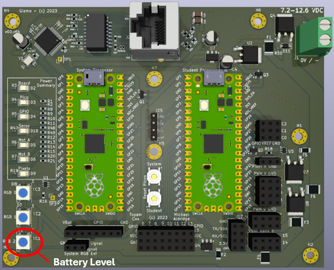
You are provided with two 7.2V NiMh batteries in your kit. Managing your batteries and their charge is a part of the competition. You must ensure that your batteries remain charged sufficiently for your robot to function properly. The Gizmo provides a battery level indicator through a single status LED which indicates the voltage level of the connected battery. The LED will illuminate Green for a fully charged battery (> TBD volts), Yellow for a battery that needs charging (< TBD volts) and Red for a battery that is insufficient to operate the robot (< TBD volts).
Gizmo power rails status indicators
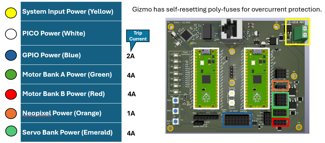
There are six power rail status LEDs on the Gizmo. These LEDs are used to indicate the voltage levels for various parts of your Gizmo. Each LED is color coded to aid in easily identifying the power subsystem that needs attention. If an LED is OFF, it indicates that the associated power rail is OFF (no voltage). This is typically due to the built-in polyfuse being tripped for that power rail; this occurs when too much current is drawn on the power rail. Polyfuses will reset automatically but can take up to 2 minutes to fully reset and return to normal state. For the motor power rails, the fuses are fast resetting and can return to normal in a matter of seconds. The diagram below shows each power rail status LED, its color, the related Gizmo ports on that power rail, and the maximum current draw before the polyfuse will trip.