The Gizmo Board
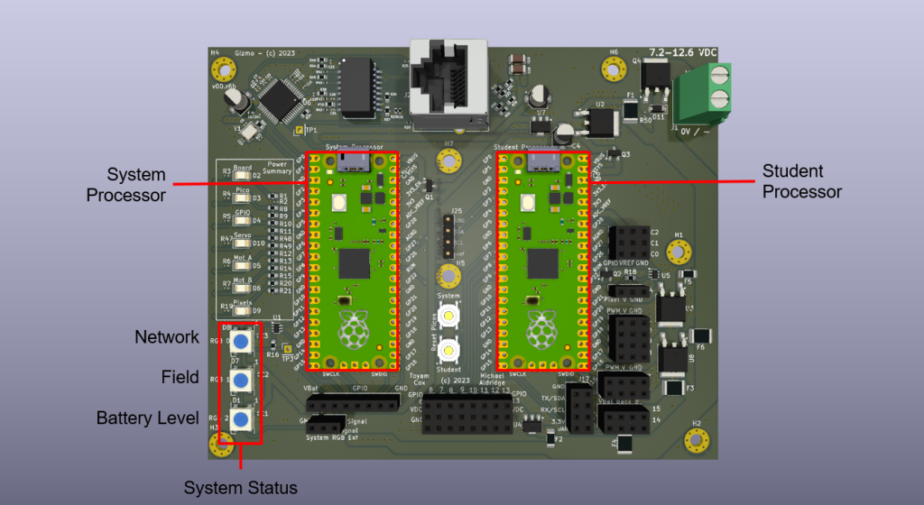
The Gizmo board is an open source carrier board that accepts two Raspberry Pi Pico micro-controller modules. These micro-controller modules, referred to as the System Processor on the left and the Student Processor on the right, make up a programmable controller that can be customized for different applications. When we refer to “Gizmo” in this lesson, it refers to the entire board including the Pico microcontrollers.
The student processor is a Pico that can interface to a variety of peripherals and runs a user-created program. The system processor is a Pico that also supports wireless communications and runs the Gizmo system firmware. The two processors communicate with each other through a serial interface.
The system processor receives data and commands wirelessly from the Gizmo Driver Station/Joystick and relays the information to the Student Processor where the user program can use the information to take action. It can also receive data and commands over an RJ45 cable for wired communications with the Driver Station/Joystick.
The system processor also maintains the 3 system status LEDs on the Gizmo that provide the user with information about the current operating state. These are the Network, Field and Battery Level LEDs. Each are multi-color LEDs which indicate various operating states through their color and blinking patterns.
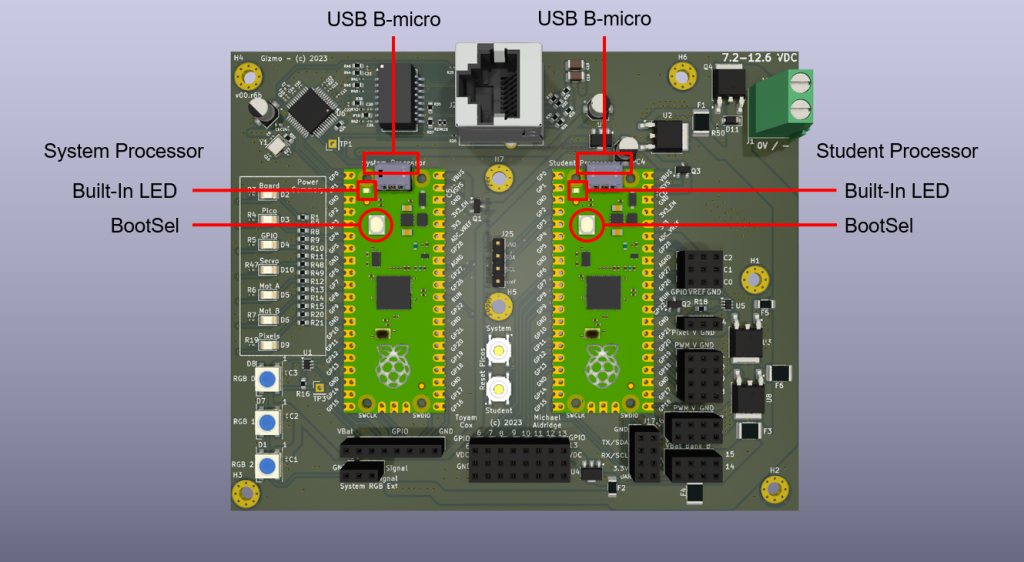
Programs are loaded onto each of the processors through the USB B-micro on each Pico. Each Pico has a special BootSel button used to establish connection to your computer when loading firmware. They also have a built-in LED that provides a visual status of the programming operations and can be used by the user program as feedback for processor activity.
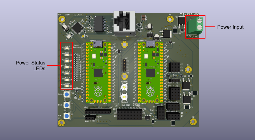
The Gizmo is powered by a 7.2v NiMh battery connected to the Power Input +/- screw terminals through an external switch assembly. The Gizmo does not contain a power switch on the board. The voltage input at these screw terminals is converted and distributed to power the various parts of the board. A series of 6 colored LEDs indicate the status of each of the voltages to the user for diagnosing power issues.
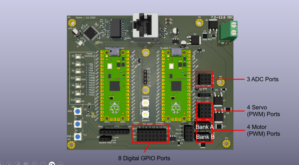
The Gizmo supports a variety of peripherals through a series of dedicated ports for digital, analog, and pulse-width modulated (PWM) devices.
The 8 digital ports (often referred to as General Purpose Input/Output – GPIO) can be programmed to act as either input or output. These ports use a voltage level of 3.3 volts. Each port consists of 3 pins, +3.3v (VDC), signal (GPIO), and ground (GND). When programmed as an input, the digital port can read the value present on the GPIO signal pin as ON (3.3v) or OFF (0v). When programmed as an output, the digital port can drive the GPIO signal pin to 3.3v (ON) or 0v (OFF). Digital ports can only represent these two possible values.
The 3 analog, or ADC (Analog to Digital Convertor), ports operate only as inputs on the Gizmo and can convert a range of voltages into numeric values. The numeric value represents the voltage level within the range, between 0v and the voltage reference (VREF). ADC ports have 3 pins, GPIO (the voltage input being measured), VREF (3.3v) and GND.
The 4 motor and 4 servo ports are of the PWM variety, intended to drive motor controllers or servos directly. Each port has a 3 pins, PWM output, Vbat (Battery voltage), and GND. The 4 servo ports are grouped together, while the motor ports are grouped in 2 banks (A & B) of 2 ports each. The unique grouping of ports is in support of the separate power busses and Gizmo’s built-in polyfuses that trip on overcurrent conditions, thereby protecting the board components from damage.
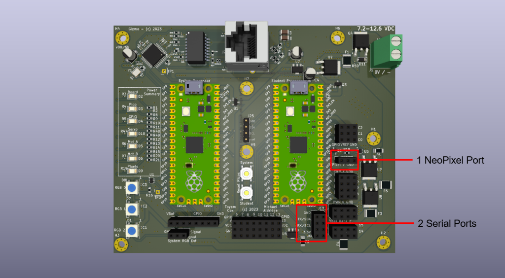
The 1 NeoPixel port allows these specialized addressable LED strips to be driven by the user program, creating some interesting lighting opportunities.
All Gizmo peripheral ports (except Motor ports) use 3-pin Dupont connectors making connections easy. Standard 3-wire male-to-male servo extensions can be used to connect peripherals. The ports are keyed so that the servo extensions cannot be inserted incorrectly. For all digital, ADC, motor, servo and neopixel ports, the ground (GND) pin is the pin closest to the outside of the board, followed by the +V (VDC, Vbat, Vref, etc.) in the middle, and then the signal pin (GPIO, PWM, Pixel) closest to the inside of the board. The motor ports have 4 pin connectors of the same order, with the 4th pin available for future expansion.
2 Serial ports are available through 4-pin headers and capable of implementing a variety of serial protocols. The 3.3v reference pin is closest to the outside of the board, followed by the serial receive, serial transmit, and ground pins.