Connecting Motors and Servos to Gizmo
Motors are connected to the gizmo using a external motor controller (MC29) from your Return Kit.
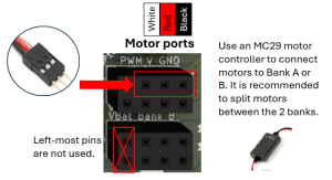
You will notice that the motor ports are divided into two groups (1-2, 3-4) or banks, number from bottom to top. You can use motors in any of the ports, but each bank has a different overcurrent setting that will disable the port when exceeded to keep from heating the PCB, wires and batteries beyond their limits. BEST motors can draw up to 4A of current each in a stall condition. A single servo bank exists, numbered 1-4 from bottom to top. Servos can draw up to 1A. The polyfuses on the Gizmo board are set to trip at the following overcurrent conditions:
Motor Bank 1 (ports 1-2): 8A (typically used for motors)
Motor Bank 2 (ports 3-4): 8A (typically used for motors)
Servo Bank (ports 1-4): 4 A (typically used for servos)
When a polyfuse trips, it can take up to 2 minutes to “cool off” and enable those ports to function again. The motor banks use fast-resetting polyfuses which will recover in about 15 seconds.
Why is this important? To design an effective robot that is not tripping the fuses and shutting down the robot to keep from “melting down”, you must take care in how you allocate your motors and servos in these connector banks to “balance the load”.
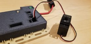
To attach a motor, first make sure that Gizmo power is off or the battery is unplugged. Now plug a motor controller’s 3-pin connector into the Gizmo on any of the motor ports 1-4. Note that the motor ports are 4-pins wide. The left-most sockets of these ports, when looking at the Gizmo with LEDs on the left-hand side, are not used; DO NOT PLUG any motor controller pin into these sockets. Install the 3-pin motor controller connector right-justified (black pin to the outside of the case when looking at the Gizmo with LEDs on the left-hand side. From left-to-right, the left pin on the motor port is unused, the 2nd pin is PWM (white wire), the 3rd pin is +BAT (red wire), and the 4th (right-most) pin is GND (black wire). The black wire on the motor controller 3-pin connector should be closest to the edge of the board. Orientation of this connector is important!
Next, attach a two-wire motor screw terminal interface to the exposed end of the motor controller. Per the BEST Competition Rules, you may attach (ONLY) blue painter’s tape around this connection to keep it from disconnecting.
Your motors may or may not already have wire leads with bare stripped ends. If they do not, you will need to carefully solder wire from your consumable kit to the motor terminal lugs; use red for the positive lead and black for the negative lead*. Now attach the black/red wires from your motor to the screw terminal connector. Unscrew (counter clockwise) each of the screws on the screw terminal connector enough to open the internal clamp; the screw should never come completely loose from the white connector. Insert each wire one at a time, making sure that there are no stray wire strands sticking out of the connector, then tighten the screw to clamp the wire and hold it in place.
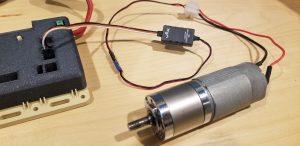
Your motor is now attached to the Gizmo through a motor controller and your program can control the motor. Repeat the same process for attaching other motors to your Gizmo in other available ports.
But which motor terminal is positive and which is negative?
BEST batteries may have a red dot on the motor indicating the positive terminal (+). The unmarked terminal is the negative terminal (-). When connected in this polarity, the motor should turn clockwise.
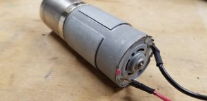
You should be aware how your motor terminals are connected, through the screw terminal interface and to the motor controller. If the wires are crossed or swapped from the expected polarity, the motor will turn in the direction unexpected. However, you can easily swap the connections at the screw terminal interface to solve the polarity issue and rotate the motor as expected.
You can connect a servo motor in any of the servo ports 5-8 on the Gizmo. The servo does not require any external components (e.g., motor controller) like a BEST motor does. Servos have a 3-wire connector that matches the 3-wire port on the Gizmo. Plug your servo into the port in the same fashion as you did with the motor controller. Insert it with the white wire on the left side of the socket, the side of the socket closest to the Gizmo power LEDs. The left pin on the servo port is PWM (white), the center pin is 5v (red), and the right pin is GND (black).